Monday 2 February 2015

Channel Types

Channel Types

Introduction:
In this blog post, I will be explaining the different channel types, what they are and whey are used for by providing justified examples as well as appropriate limitations. The media/mediums include:
  • Light
  • Radio
  • Microwave
  • Satellite

In summary, different types of devices uses different types of mediums and these are the methods to how they transfer data. Each medium have their own strengths and weaknesses and this can dictate to how reliable they are.

Light:
The medium ‘light’ can be found in fibre optics only for the time being because it is a newer technology. Out of the entire medium list, light is extremely fast in fibre optic due to a various amount of factors. Firstly, it does not interfere with anything else and nothing interferes with it because it does not use electrical signals alike telephone link does. What makes light reliable is that it attempts to keep its data throughout its journey, making it suitable for emergencies and for larger files as data can be transferred much faster.

However, the weakness of light is that it has a flaw where it will refract even within the glass material; this allows it to only travel a certain amount of distance before it begins to wear off. Additionally, as mentioned above light is a new technology invented recently, which means that the costs are relatively high (lowered as the demand increases).

Radio:
Radio is a very common medium type that has a high frequency rate – this allows data to travel to farer destinations than other mediums. These properties allow it to be used in emergency services such as by police, rescue teams, fire fighters, and ambulances to get quick responses in remote areas of a country. An example would be when a person got stuck in an unknown location; the person could use a walkie talkie (supports radio) to send contact for help – making it a reliable way of communicating between two parties.

Despite its usefulness, it can also have weaknesses. One limitation would be that other signals and interferences from other transmission methods may interfere with it and therefore it will lose its quality – hence the crackles. This can waste potential time and thus be a time consumer.

Microwave:
Microwave is a channel type medium that is suitable for high amounts of bandwidth. Its wavelength is not as long as radio but it has a slight difference in frequency. An example of a usage is it transmits communications such as phone calls if it is in range because the satellites that is in orbit.

There are not many limitations for microwaves. However, as like the other transmission methods and the mediums of the channel types, it is still vulnerable to interference. Furthermore, microwaves can be a harmful substance to parts of our bodies, such as our brain. This is because the chips are found in our mobile phones and making many phone calls means the exposure to our heads are more common.

Satellite:
Satellite is another channel type that is super-efficient and reliable for the transfer of data from one country to another around the world at an appropriate time. Satellites also cover a humongous geographical surface area and can transfer the information to many buildings, known as telecommunications (different types of data transmissions such as voice and video data channels). An example of this would be broadcasting a television show to specifically a small area only. The limitations of satellite are its cost and maintenance for its start-up production despite its reliability. Additionally, the time it will need to be repaired will be time consuming too. The strengths balances out well with its weaknesses overall.

Harvard Referencing: (In order of reference)
- Anderson, K. Atkinson-Beaumont, D.Kaye, A. Lawson, J. McGill, R. Phillips, J and Richardson, D. 2011. Information Technology Level 3 Book 1 BTEC National. Harlow: Pearson Education Limited.


Bibliography: (In alphabetical order)
- darvill.clara, n.d. Microwaves. [Online] Available at: <http://www.darvill.clara.net/emag/emagmicro.htm> [Accessed 02 February 2015].

Data Transmission

Data Transmission

Introduction:
In this blog post, I will be explaining the different types of factors for data transmissions and what they do overall. Additionally, I will give examples to the content and provide limitations of each data transmissions wherever possible. These include:
  • Bandwidth
  • Noise
  • Compression

When data is split into packets and are sent across a network, there are many factors mentioned above that can affect the transmission of data in a positive or negative way such as its quality in general.

Bandwidth:
During the transfer of data, data is sent using bandwidth and it is essentially how fast it is transmitted from the sender device to the recipient device within a certain time. The amount of bandwidth can be based upon the network type used, such as wireless or wired. In a wireless the network, a limitation for bandwidth is it may be noticeably slower because the Wi-Fi travels through air to the device whilst being affected by potential interferences such as obstacles and by the adjacent signals in the surroundings. Another limitation of this is also to do with speed because the amount of users on a router can also dictate how much bandwidth you receive, this is because the router is the device in the network infrastructure that divides the bandwidth by the amount of users for an equal and fair amount. Furthermore for wired networks, bandwidth is indeed faster and a more reliable method of sending data because of the usage of cables e.g. Ethernet avoids interferences and prioritises the device alone.

Other than factors of network choice, services and applications ran on the device can be another limitation that affects the overall bandwidth. An example would be the Skype application (VoIP – voice over internet protocol) which the network will attempt to ensure perfect connection by prioritising the user’s device to have the most internet bandwidth. As a result, this affects other people nearby that are using the same wireless network and may cause a bottle neck (constant traffic of data collision). Resultantly, the benefits of this are that it avoids delays and therefore no data are lost, being an efficient and reliable approach.

Noise:
Noises are another way of referring to interferences by either internally or externally. A common example of an external noise is background noises “caused by metal-framed buildings (causing reflection and acting like a Faraday cage)” (Anderson et al, 2011). This is because the conductor material used in construction can be a way of attracting electrical pulses. Other than buildings interfering, any transmission method without the use of shielding (such as UTP) can also be affected internally and externally altogether. Furthermore, regarding about copper cables such as STP (shielded twisted pair) requiring electrical-magnetic to send data, the closeness of the cables can also interfere with the adjacent wire making it a limitation. Lastly, fibre optic cables are composed of very thin glass for the fastest and most reliable speed, however this means that the thinness of the material can allow other interferences to again to affect it.

Compression:
During data transmission, compression techniques can be applied to lower the file size and still remain the original quality of the file for easier transport – this is because it will then require fewer packets to be sent and checked across a network. Compressions are mainly found in networks that have a lower bandwidth for more effectiveness. Familiar examples include “applications, games, images, videos, and audio” (Anderson et al, 2011).

Despite these criticisms, Huffman coding is applied to many scenarios. It is an effective method of compressing a specific text such as individual alphabets, symbols and numbers by assigning the most frequent characters to a specific sequence binary code. This it to lower the amount of bandwidth required to send a piece of data.

Take this piece of text as an example “Hello, how are you?”
As you can see in the table, the most used character has been assigned to the lowest code for the quickest speed, (see table 1).

Table 1
Character
Frequency
Huffman Code
O
3
0
‘ ‘
3
1
H
2
01
E
2
10
L
2
11
A
1
000
U
1
001
R
1
010
W
1
011
Y
1
100
,
1
101
?
1
11

However, the drawback and limitation of Huffman coding is that the text message needs to be encoded and assigned the shortest code at the start and to be decoded at the end every time because Huffman coding is not fixed unlike ASCII - this may take time but it will help the speed of the process throughout.

Harvard Referencing: (In order of reference)
- Anderson, K. Atkinson-Beaumont, D.Kaye, A. Lawson, J. McGill, R. Phillips, J and Richardson, D. 2011. Information Technology Level 3 Book 1 BTEC National. Harlow: Pearson Education Limited.

Error Detection & Error Correction

Error Detection & Error Correction

Introduction:
In this blog post, I will be explaining the different types of error detection and error correction and identify what they are used for. I will also provide examples and identify suitable limitations whereas possible. The error detections and error corrections are:
  • Parity Check (Good)
  • Checksums (Better)
  • Cyclic Redundancy Check (Best)

Overall, the different types of error detection and error correction are techniques for identifying whether the data file is corrupted or not whilst data is being sent across a network. It checks the quality of the data and this may help solve the issue depending on which method used.

Parity Check:
Parity checking is the most basic technique for error detection and error correction and uses mainly the 8th bit for checking within the data packet. Before it performs the check to each individual bit in the packet, a protocol must be in place to decide whether it performs odd parity check or even parity check (assume the recipient device has the protocol check set to odd) - This method checks whether the amount of bits are even or odd in the packet.

In this example for when the data is sent, it will recheck the whole data packet to see if it has got an odd or an even amount of bits. In the end, if the total amount of bits are odd to begin with (which fits with the protocol), it will allow and accept the data to be received by the device. However, if it is even instead (somehow data corruption must of occurred midway its journey whilst sending) then error is detected because there is an even amount of 1’s. To correct this, the recipient device will reject the packet as a whole and will signal another request to the original device to resend – this process then repeats until the data is set correctly.

However, despite this effective procedure there is a big limitation that weakens this technique from the rest – data can bypass this protocol if there are two or more interferences to the bits within the packet. For example, the parity check is expecting there to be five 1’s and three 0’s but data got corrupted and ended up with seven 1’s and one 0. The amount of binary 1’s are still odd but the amount is incorrect, however parity checking does not correct this and thus allows the data to be passed (a limitation). As a result, the data will be accepted but the file will have some corruption in some areas. This can make it unreliable as the chance of this occurring in a large file transfer is higher, (see parity check table example below).

Parity Check Table Example:

Step 1: Packet example (protocol parity check is set odd, does not include the 8th bit).
1
1
0
0
1
1
1
1

Step 2: The bit in the packet becomes corrupted.
Step 3: The 8th bit at the end is used and is turned into a 0 because the number of odds does not correspond with the validation as it is even.
Data Received
1
1
0
1
1
1
1
1
Parity Checks
1
1
0
1
1
1
1
0
Step 4: The data is not odd as the 8th bit is changed, checksum here is taken place.
Step 5: Recipient device requests the data packet to be resent.
Step 6: Packet is resent (Error Correction).
Data Received
1
1
0
0
1
1
1
1
Parity Checks
1
1
0
0
1
1
1
1
Step 6: Data is correct because it is odd. Data passes.

Limitation of Parity Check:

Step 1: The limitation is that the data can still pass through the parity check even if there are two errors with two bits as it has changed/corrupted.
Original Data
1
1
0
1
0
1
1
1
Data Received
1
1
0
0
1
1
1
1
Parity Checks
1
1
0
1
0
1
1
1
Step 2: The data is incorrect, but it still passes through because it fits the odd binary protocol.

Checksums:
Checksum is another technique for error detection and error correction that provides a more quality check for data transmission along a network (more complicated). How this works is that it firstly adds up the total amount of bits for a data packet and is then divided by a fixed divisor (number) often set by the network server. Usually this calculation is very precise and therefore will always result in a sum (known as quotient and are not used much after as the remainder is what makes checksum unique) and a remainder; this remainder will be taken and sent along with the packet data to the recipient device.

Furthermore, on the other end where the device receives this data, it will perform checksum and redo the previous sum to identify whether the remainder is identical. If the remainder is identical then this proves that there is no data corruption. However, if the remainder is different, then error has been detected and will therefore be corrected as it will request a signal back for the sender device to resend the packet again, (see below for example).

Checksum Example:
Total Amount of Bits/Data = 22.
Fixed Divisor = 4.
Calculation: 22 divided by 4.
Quotient = 5.
Remainder = 2
(uses and checks remainder).

Moreover, the limitations for this are that “checksum is the older of the two programs” (www.differentbetween.net/, 2014) comparing to CRC, this is because checksum was first created and therefore have become outdated when it was surpassed by CRC. Another limitation is that checksum can only use its technique on data packets that has approximately 8 bytes maximum and thus only being able to identify errors to individual bits rather than multiple at one time.

Cyclic Redundancy Check (CRC):
Cyclic Redundancy Check is essentially a combination of both parity check and checksum as explained above. However, the only difference to checksums is that it uses the polynomial formula (similar to the checksum example). This allows CRC to perform a more complicated and thorough check “based on 16- or 32-bit” (www.differencebetween.net/, 2014) meaning that this technique was created to identify a larger amount of data errors at one time as it covers more bits. This makes it more reliable than checksum as a result for larger files. One limitation can be speed because CRC may require more time to thoroughly perform error detection and error correction.


Harvard Referencing: (In order of reference)
- Anderson, K. Atkinson-Beaumont, D.Kaye, A. Lawson, J. McGill, R. Phillips, J and Richardson, D. 2011. Information Technology Level 3 Book 1 BTEC National. Harlow: Pearson Education Limited.
- differencebetween, 2014. Differences Between CRC and Checksum. [Online] Available at:  <
http://www.differencebetween.net/technology/software-technology/differences-between-crc-and-checksum/> [Accessed 01 February 2015].

Synchronous & Asynchronous Transmission

Synchronous & Asynchronous Transmission

Introduction:
In this blog post, I will be explaining about what synchronous and asynchronous transmission are and what they do; I will also provide examples of each and identify limitations that are relevant when explaining the content.

In general, both of these transmissions are there to determine how data are sent overall. What makes these transmissions different from each other and how fast data is sent all depends on whether they have clocking signals or no clocking signals (synchronisation). Clocks are essentially a speed rate of how many bits are sent at a set time - they are both serial (where one byte is sent right after another).

Synchronous Transmission:
Synchronous transmission is a method where both the sender and recipient devices are synchronised, this means that data sent are sent at regular intervals and must be both online on the internet for information to be sent and communicated. Furthermore, this makes it reliable because the flow of data is sent at a considerable rate – usually set by what is known as a clock that uses clocking signal.

An example of this would be voice to voice channels on Skype – where two users must be online and in a call for them to be able to communicate. Another example would be a DCE such as “a router, WAP or switch” or even modems due to its functionality on bandwidths because it usually sends multiple bytes at one time (the DCE allows the clocking signal to be more rapidly).

However, the limitations of synchronous is that this transmission method needs requires both sides to be available or otherwise it will not work – one person may be busy or could be around the world with a different time zone overall and this can make it extremely inconvenient and unreliable. Lastly, for synchronous transmission to take place, it will be at a higher cost.

Asynchronous Transmission:
Hence the ‘A’ in front of the word it means that it is unlike synchronous transmission. Whereas synchronous uses clocking signals, asynchronous does not and instead sends data whenever by using a “start bit and stop bit” (www.computerhope.com/, 2015) that informs the device when to start sending and when to stop. An example of this transmission method is emails sent from the client to the recipient. The recipient does not have to be available but however the email will still arrive to the inbox successfully and can be replied at any time – not required both parties to be synchronised.

On the other hand, one limitation to this is that it requires the other recipient device to give an acknowledgement (confirmation) that it can then send data, relating to slower speed. Another common example such as computer to a printer (serial) would be asynchronous due to having a one way system. Despite all these limitations, one benefit would be its low cost.

Harvard Referencing: (In order of reference)
- Anderson, K. Atkinson-Beaumont, D.Kaye, A. Lawson, J. McGill, R. Phillips, J and Richardson, D. 2011. Information Technology Level 3 Book 1 BTEC National. Harlow: Pearson Education Limited.
- computerhope, 2015. Asynchronous. [Online] Available at: <
http://www.computerhope.com/jargon/a/asynchro.htm> [Accessed 31 January 2015].


Bibliography: (In alphabetical order)
- sites.google, n.d. Discuss the advantages and disadvantages of synchronous and asynchronous transmission. [Online] Available at: <https://sites.google.com/site/assignmentssolved/mca/semester3/mc0075/13> [Accessed 31 January 2015].

Binary, Bits & Bytes

Binary, Bits & Bytes

Introduction: 
In this blog post, I will be explaining what binary, bits, and bytes are and how they fit with packets and frames in the process of encapsulation. Furthermore, I will also be identifying any limitations and provide examples and or diagrams where relevant to help expand on the overall knowledge.

Binary, Bits & Bytes:
Binary is the computer’s language which is composed of 1’s or 0’s, this indicates whether it is on or off, true or false and more (an example of binary is ASCII as it assigns each number/alphabet an unique binary code depending on how often it is used – read more about ASCII in my other blog post ‘Data Transmission’).

However, within binary, there are bits and this makes it the smallest part of an information as a whole. When eight bits are put together, it will form to become a byte which is a piece data (smallest piece a computer can send). These pieces of data can range from addresses to sequencing to even the file. Depending on the packets, the 8th bit is usually would be used for error checking when the recipient device receives it and if data corruption is detected, an acknowledgement/permission would be sent for the sender device to resend the packet.

Moreover, there are different file sizes depending on how many bits/bytes there are. For example, a kilobyte is composed of 1000 bytes (technically 1024 because data can never be stored accurately) and a megabyte is 1,000,000 bytes and so forth to even gigabytes. In summary, the larger the file the more bytes will be needed, (see figure 1).

Figure 1: Binary
Packets & Frames:
Binary, bits and bytes are related to packets because in the process of packet switching, the larger file is broken down into manageable chunks also known as packets to be sent across the network. One packet contains bytes (information and data elements mentioned above) and is used to avoid data corruption as well as to save time so the whole file does not have to be resent as a whole Furthermore, for the packet to be sent accordingly and safely, it is separated and encapsulated by frames on each side, (see figure 1).

The limitations of packets and frames are the speed – although it is a fast way of sending data the packets can only hold a limited amount of bytes of roughly 64KB. So if the packets were over 64KB it would require two packets. In a larger file, this can then slow down the whole process.

Harvard Referencing: (In order of reference)
- Figure 1: Chan, D. 2015. Binary, Bits, Bytes & Packets, Frames. [Accessed 31 January 2015].


Bibliography: (In alphabetical order)
- Anderson, K. Atkinson-Beaumont, D.Kaye, A. Lawson, J. McGill, R. Phillips, J and Richardson, D. 2011. Information Technology Level 3 Book 1 BTEC National. Harlow: Pearson Education Limited.

Analogue vs Digital

Analogue VS Digital

Introduction:
In this blog post, I will be explaining what the analogue is in general as well as digital and what makes them different from each other. Furthermore, as each is different I will identify its limitations where relevant and provide examples of each example of signals.

Analogue:
Analogue in general is the form of data humans interpret, such as sound and music. For example, if you record someone speaking or singing, usually a device of some sort such as an oscilloscope will display a very natural sine waveform, (see figure 1). Furthermore, the cables are very sensitive to high currents such as from AC (alternating current) and therefore uses DC (direct current) for the device’s components to not over heat. However, AC has a high voltage to keep it accurate.

In more depth within the analogue’s waveforms, there are many different types which include:
  • Amplitude: The power of a wave; from the peak (maximum disturbance) to the line where it started from (undisturbed disturbance). This defines the loudness which corresponds to it; meaning that as the sound gets louder, so will the amplitude (height). An example would be a loud thump and this will result in a very tall amplitude when it is shown.
  • Frequency: Is how frequent the wave pattern repeats itself within a second from point of a wave to another in a repetition. An example is a very fast paced music which will result in a high frequency rate as more waves are compressed within the second; this means a lot of sound is being made. Moreover, different types of waves can also determine the frequency used.
  • Wavelength: A wavelength is a single point of a wave (cycle) to the next exact point on the other. A wavelength can sometimes be useful for measuring how long a waveform is, hence the name given.
  • Cycle: Is a single point of a wave (wavelength) to the next exact point on the other. Cycles can be useful for determining whether the signal is a low frequency or if it is a high frequency – “A low frequency signal has a small number of cycles per second; a higher frequency signal can have billions of cycles per second”, (Anderson et al, 2011).
  • Period: Carries out the same properties and measuring method of a cycle and or wavelength, however the only difference is that the two specific points can be anywhere on the analogue wave. This can be a way of sampling a specific range.
With analogue waves, the accuracy increases greatly but the limitations of these results in larger file size. This makes it inconvenient and would be difficult to distribute music for example. Another limitation of analogue is that it is very sensitive to sound such as background noises, picking up unnecessary sounds that may potentially increase the file size – this distorts it.

Figure 1: Analogue Waveforms
Digital:
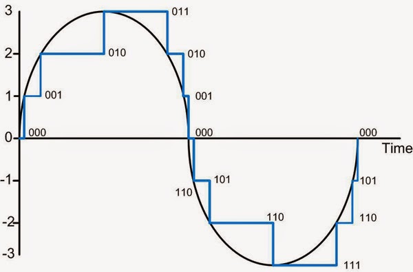
However, on the other hand the limitations can be solved by converting analogue waves to digital format. To do this, it requires the excessive use of sampling rates – these are essentially points placed on an analogue wave which allows a digital reconstruction for the devices to store in (see figure 2), an example would be the .MP3 file stored in an MP3 player after conversion.
Figure 2: Analogue Conversion Digital

Figure 3: Analogue Sampling


Consequently, the limitations of digital is that the accuracy of the analogue waves are lost during conversion, removing the ability for our human ears to be able to hear as precise, thus the excessive use of sampling would also increase the file size overall too. To combat this, filters such as ‘Flac’ can be applied to the digital reconstruction to make it similar to the actual analogue wave when played back, this is because it is provides lossless for the quality.

Devices such as a computer can read binary numbers made up of 1’s and 0’s and that is what sampling does, by assigning each sample a code, (see figure 3). Moreover, it is necessary for analogue to be encoded digitally for it to be stored in devices such as a smartphone. Another primary usage of digital is that it can be easily manipulated with the help of software’s like Audacity where the frequency and amplitude can be altered etc. Then lastly, for example when a music file is stored digitally on a MP3 player, when it plays back it will convert it back to analogue with little quality lost.

Harvard Referencing: (In order of reference)
- Anderson, K. Atkinson-Beaumont, D.Kaye, A. Lawson, J. McGill, R. Phillips, J and Richardson, D. 2011. Information Technology Level 3 Book 1 BTEC National. Harlow: Pearson Education Limited.
- Figure 1: Chan, D. 2015. Analogue Waveforms. [Accessed 26 January 2015].
- Figure 2: streaming.wisconsin, n.d. Analogue Wave. [Online] Available at: <
http://streaming.wisconsin.edu/images/audio_editing_SF_images/sf00sample.gif> [Accessed 26 January 2015].
- Figure 3: screaminfx, n.d Analogue Verses Digital. [Online] Available at: <
http://screaminfx.com/images/tech-images/what-is-analog-verse-digital-explanation.jpg> [Accessed 26 January 2015].

Bibliography: (In alphabetical order)
- bbc, 2014. Amplitude, Wavelength and Frequency. [Online] Available at: <http://www.bbc.co.uk/schools/gcsebitesize/science/aqa_pre_2011/radiation/anintroductiontowavesrev2.shtml> [Accessed 26 January 2015].
- webopedia, 2015. Digital. [Online] Available at: <
http://www.webopedia.com/TERM/D/digital.html> [Accessed 26 January 2015].